
Page 21 - Catálogo de Mangueiras e Conexões Hidráulicas, Adaptadores e Acessórios
P. 21
Diretrizes dos Acessórios
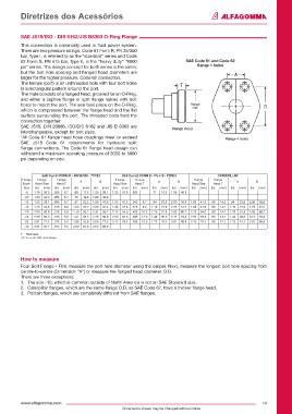
sAe J518/Iso - DIs 6162/JIs B8363 o-Ring Flange
This connection is commonly used in fluid power system.
There are two pressure ratings. Code 61 Form R, PN 35/350
bar, Type I, is referred to as the “standard” series and Code
62 Form S, PN 415 bar, Type II, is the “heavy duty“ “6000 sAe Code 61 and Code 62
psi” series. The design concept for both series is the same, flange 4 holes
but the bolt hole spacing and flanged head diameters are
larger for the higher pressure, Code 62 connection.
The female (port) is an unthreaded hole with four bolt holes
in a rectangular pattern around the port.
The male consists of a flanged head, grooved for an O-Ring,
and either a captive flange or split flange halves with bolt
holes to match the port. The seal take place on the O-Ring, Flange
which is compressed between the flange head and the flat O.D.
surface surrounding the port. The threaded bolts hold the
connection together.
SAE J518, DIN 20066, ISO/DIS 6162 and JIS B 8363 are
interchangeable, except for bolt sizes. Flange Head
*All Code 61 flange head hose couplings meet or exceed Flange 4 holes
SAE J518 Code 61 requirements for hydraulic split
flange connections. The Code 61 flange head design can
withstand a maximum operating pressure of 3000 to 5000
psi depending on size.
sAe Cod 61 FoRM R - PN 35/350 - TYPe I sAe Cod 62 FoRM s - PN 415 - TYPe II CATeRPILLAR
Flange Flange Flange A B Flange Flange A B Flange Flange A B
Dash Head Size Head T Head Size Head T Head Size Head T
Size (in) (mm) (in) (mm) (in) (mm) (in) (mm) (in) (mm) (in) (mm) (in) (mm) (in) (mm) (in) (mm) (in) (mm) (in) (mm) (in) (mm)
-8 1.19 30.2 .265 6.7 .69 17.5 1.50 38.1 1.25 31.8 .305 .71 18.2 1.59 40.5
-10* 1.34 34.0 .265 6.7 .78 19.8 1.69 42.9
-12 1.50 38.1 .265 6.7 .87 22.2 1.89 47.6 1.63 41.3 .345 8.7 .94 23.8 2.00 50.8 1.63 41.3 .56 14.2 .94 23.8 2.00 50.8
-16 1.75 44.5 .315 8.0 1.03 26.2 2.05 52.4 1.88 47.6 .375 9.5 1.10 27.8 2.25 57.2 1.88 47.6 .56 14.2 1.10 27.8 2.25 57.2
-20 2.00 50.8 .315 8.0 1.19 30.2 2.31 58.7 2.13 54.0 .405 10.3 1.26 31.8 2.63 66.7 2.13 54.0 .56 14.2 1.26 31.8 2.63 66.7
-24 2.38 60.3 .315 8.0 1.41 35.7 2.75 69.9 2.50 63.5 .495 12.6 1.44 36.6 3.13 79.4 2.50 63.5 .56 14.2 1.44 36.6 3.13 79.4
-32 2.81 71.4 .375 9.5 1.69 42.9 3.06 77.8 3.13 79.4 .495 12.6 1.73 44.4 3.81 96.8 3.13 79.4 .56 14.2 1.73 44.4 3.81 96.8
-40 3.31 84.1 .375 9.5 2.00 50.8 3.50 88.9
T = Thickness
-10 is a non SAE size flange
how to measure
Four Bolt Flange - First measure the port hole diameter using the caliper. Next, measure the longest bolt hole spacing from
centre-to-centre (Dimension “A”) or measure the flanged head diameter. O.D.
There are three exceptions:
1. The size -10, which is common outside of North America is not an SAE Standard size.
2. Caterpillar flanges, which are the same flange O.D. as SAE Code 62, have a thicker flange head.
3. Poclain flanges, which are completely different from SAE flanges.
www.alfagomma.com 19
Dimensions shown may be changed without notice